Опубликовано19.03.2026
Обновлено11.05.2026
Другие модели автора
Все модели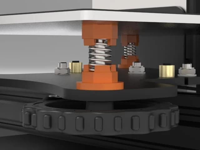
Скачать BFPTouch - Бедняк BLtouch. Простой, дешевый, аккуратный, точный, компактный и надежный Z Proble для выравнивания любой поверхности. — 3D-модель для печати на 3D-принтере
Скачать BFPTouch - Бедняк BLtouch. Простой, дешевый, аккуратный, точный, компактный и надежный Z Proble для выравнивания любой поверхности. — 3D-модель для печати на 3D-принтере. Файл загружен автором Katalog3D на маркетплейс Каталог3Д и доступен для скачивания в формате STL или 3MF.
Лицензия. Перед использованием ознакомьтесь с условиями лицензии в карточке модели. Одни файлы разрешают только личную печать, другие — коммерческое использование. Подробнее — в разделе лицензии.
Смотрите также: другие модели этого автора, похожие файлы по тегам — cheap, bed leveling, 9g servo, sensor, BLTouch, hypercube evolution, optical endstop, z probe.
