Опубликовано27.03.2026
Обновлено29.05.2026
Другие модели автора
Все модели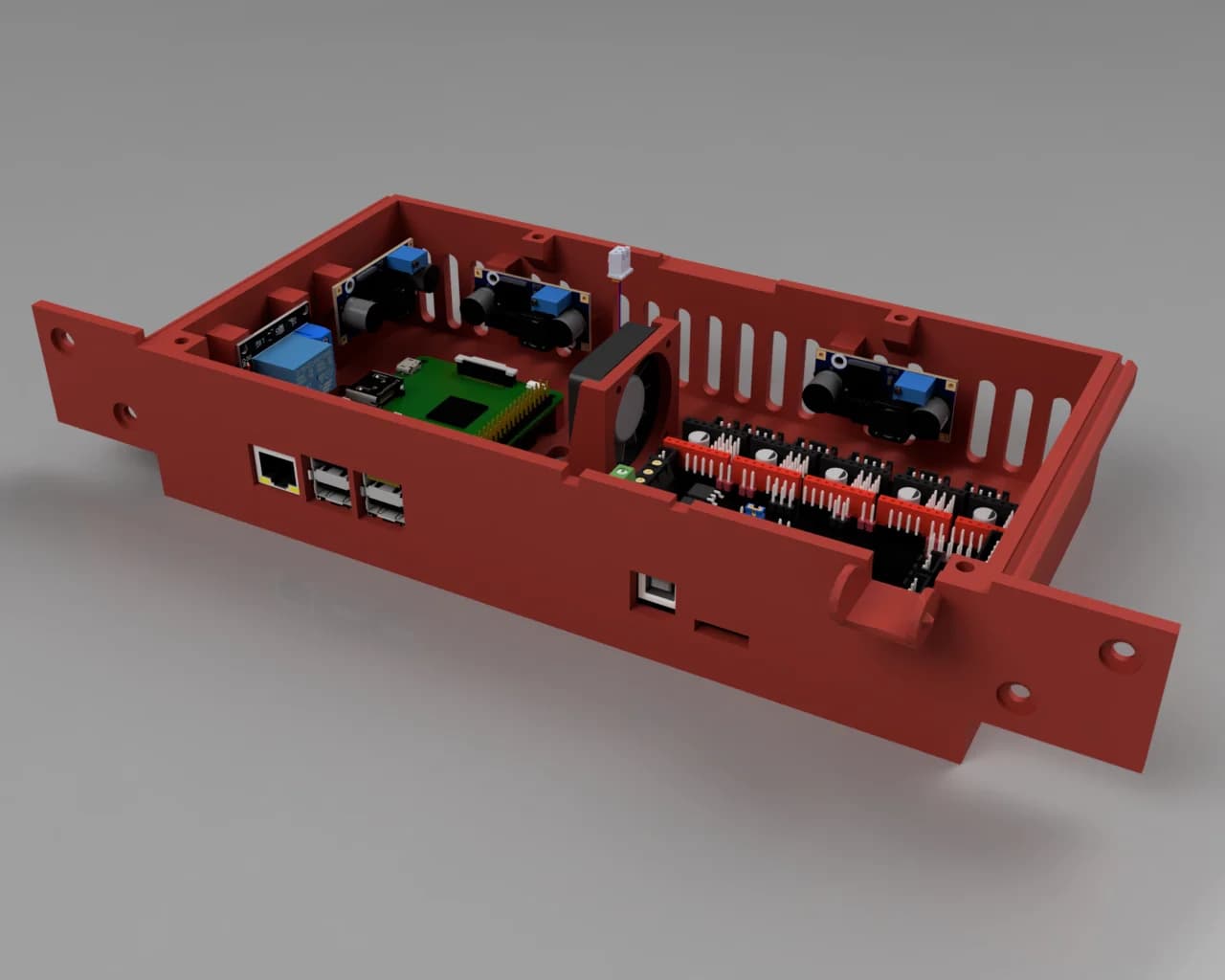
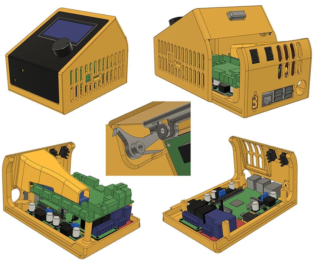
Скачать Корпус для внешней электроники Ender 3 V2 — 3D-модель для печати на 3D-принтере
Скачать Корпус для внешней электроники Ender 3 V2 — 3D-модель для печати на 3D-принтере. Файл загружен автором Katalog3D на маркетплейс Каталог3Д и доступен для скачивания в формате STL или 3MF.
Лицензия. Перед использованием ознакомьтесь с условиями лицензии в карточке модели. Одни файлы разрешают только личную печать, другие — коммерческое использование. Подробнее — в разделе лицензии.
Смотрите также: другие модели этого автора, похожие файлы по тегам — case, creality ender 3, Ender-3, коробки, Ender, Raspberry Pi, raspberry pi case, electronics enclosure, enclosure, skr 13, bigtreetech skr, external, SKR, SKR V13.